Chapter 1 Dimensional Analysis, Vector Differential Operators, and Electrostatic
Click on image to get to the problems.
Problem 1. Dimensional Analysis and Unit Law
Problem 2. The Gradient of Scalar Function
Problem 3. The Divergence of Vector Function
Problem 4. The Curl of Vector Function
Problem 5. Electric Potential of Conservative and Non – Conservative E-Fields
Problem 6. Static Electric Fields
Problem 7. E-near-fields of Electrically Short Non-conducting Rod
Problem 8. E-near-fields of Electrically Short Dipole
Problem 9. E-fields of Electrically Short Two-wire Line
Problem 10. E-field around Two Parallel Conductive Wires of Circular Cross-sections
Problem 11. Uniformly Charged Sheet
Problem 12. Uniformly Charged Disk
Problem 13. The Static Model of a Capacitive Top-hat Element of the Current Radiator
Problem 14. 2D Capacitor with Circular Plates
Problem 15. 2D Parallel Strip Model of Capacitor
Problem 16. Potential and Field Distribution in Microstrip Line (2D Static Model)
Problem 17. Faraday Cage
Chapter 3 POYNTING THEOREM. TWISTED BEAMS. FOSTER's REACTANCE and LORENTZ's RECIPROCITY THEOREMS
Click on image to get to the problems.
Problem 1. Twisted LG (Laguerre-Gaussian) Circularly Polarized Beam
Problem 2. Bouncing back and forth Electric and Magnetic Energy in LC Resonance
Problem 3. Circuit Cavity Resonator of Rectangular Shape
Problem 4. The Field at Sharp Edges of Metal Cube
Problem 5. The Field at Sharp Edges of Metal Cone
Problem 6. Influence Conductive Surface Curvature on Electric Charge and Current
Problem 7. Distribution Smith Chart from Scratch
Problem 8. Foster’s Reactance Theorem. Ladder-Type Network
Problem 9. Lorentz’s Reciprocity Theorem
Problem 10. Poynting’s Vector and Hand Mnemonic Right-Hand Rule (RHR)

MATLAB FILES
Click on image to get to the files.
Chapter 2 Interaction E- and H-fields with Material Media. Metamaterials. Boundary Conditions. Eddy Current
Click on image to get to the problems.
Problem 1. Rotation of Ball-and-Stick Model of Electric Dipole in Uniform E-field.
Problem 2. Rotation the Loop Carrying Steady Current in Uniform B-field.
Problem 3. Polarized Conductive Sphere in Uniform Electric Field.
Problem 4. PolarizedDielectric Sphere in Uniform Electric Field.
Problem 5. Electric Potential and Field due to Charge Placed above Plane Dielectric Boundary(Dielectric-Dielectric Interface with no free charge).
Problem 6. Electric Potential and Field due to Charge Placed above Perfect Conductive Plane (Dielectric-PECInterface).
Problem 7. Magnetic Potential and Field due to Line Current Placed above Plane Permeable Half-Space
Problem 8. Line Charge outside Dielectric Cylinder
Problem 9. Passive Magnetic Shielding. Cylindrical Shell with Permeable Core in Uniform External Magnetic Field.
Problem 10. Superconducting Disk in External Uniform Magnetic Field
Problem 11. Superconducting Sphere in External Uniform Magnetic Field.
Problem 12. Electrically Anisotropic Crystal
Problem 13. Hysteresis (B-H) Loop
Problem 14. Drude-Lorentz’s Model of Metal Dielectric Constant.
Problem 15. Illustration of Atom Electric Polarization
Problem 16. Force Precession in Fully Magnetized Ferrite
Problem 17. Eddy-Current Brakes Model
Problem 18. Bar Magnet Traveling through a Conducting Pipe
Problem 19. Eddy Current on Copper Disk in Uniform Magnetic Field of 50 Hz
Problem 20. Effect of Electromagnetic Cloaking/Hiding Copper Cylinder (shown in yellow) by the Layer of Anisotropic
Problem 21. Inhomogeneous Metamaterial (yellow)
Chapter 6 FEED LINE BASICS
Click on image to get to the problems.
Problem 1. Introduction to Rectangular Waveguide (WR)
Problem 2. Power Handling by Rectangular Waveguide
Problem 3. Introduction to Circular Waveguide (WC)
Problem 4. Rectangular (WR) and Circular (WC) Waveguide Comparison
Problem 5. Two-wire Ribbon-type Line
Chapter 1 Magnetostatic
Click on image to get to the problems.
Problem 1. H-fields due to a steady electric current carried by the infinitely long conductive wire in the z-direction
Problem 2. H-fields due to a steady electric current carried by two infinitely long non-magnetic perfectly conducting wires in the z-direction
Problem 3. H-fields due to a steady electric current carried by the infinitely long conductive rectangular wire in the z-direction
Problem 4. E- and H-fields produced by a finite wire with the steady filamentary current
Problem 5. H-fields due to a steady electric current carried by the circular loop/coil of conductive wire
Problem 6. H-fields due to a steady electric current carried by the rectangular loop of conductive wire
Problem 7. H-fields due to a single layer solenoid carrying a steady electric current
Problem 8. Wireless power transmission (WPT) through inductive coupling
Problem 9. Faraday’s Law of Electromagnetic Induction and Lenz’ Law. Magnet moving through a coil
Chapter 4 SOLUTION OF BASIC EQUATIONS OF ELECTRODYNAMICS
Click on image to get to the problems.
Problem 1. Top-hat Dipole Radiation
Problem 2. Electrically Small Current Loop Radiation
Problem 3. Huygens’ Radiator Radiation
Problem 4. Skin Effect
Problem 5. Charge Moving with Constant Speed along X-axis
Problem 6. Linear Polarized Plane Wave Propagation in Free Space.
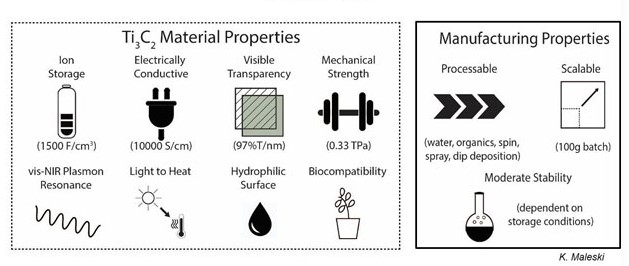
MXene Layer as Metamaterial with Complex Permeability and Permittivity in X-Band
1. Multilayer MXene stab should behave as a Metamaterial with complex permittivity and permeability
2. Since the energy stored in the near-field electrical fields much exceeds magnetic fields, i.e. ????????≫????????, we can expect that the relative dielectric and magnetic constants are ????r ≫ ????r
Click on image to get to the text.
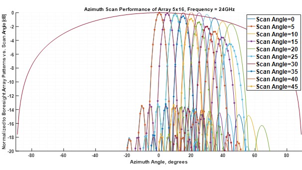
5G Broadband Back-fed Stacked Radiator on Rohacell Substrate, and 5x16 Array Thereof
The phased antenna array is one of the lead front-end components of current and coming 5G communication systems that define their massive MIMO performance. The trend outlined in recent years is to provide “… a robust and complete platform/wizard for RF/microwave engineers … “ to “… develop … more capable antenna and other RF front-end components in less time than before.” “Benefits of systems operating at mmWave frequencies include the small sizes of antennas and the larger available bandwidth.” Regrettably, a wide variety of application-driven requirements (city or rural environment, a realized gain, scan and polarization performance, impedance matching, etc.) cannot be met by a single and forever designed element.
Click on image to get to the text.
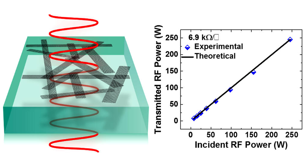
Functionalized Graphene Nanoribbon Films as a Radiofrequency and Optically Transparent Material
Radiofrequency (RF) transmissions are used in a wide range of communication applications such as antennas and radomes, mobile services, and global positioning systems. We recently reported RF-transparent, electrically conductive hexadecylated graphene nanoribbon (HD-GNR) films for targeted voltage induced deicing of RF equipment such as radar domes (radomes) and phased array antennas.1 A large-scale HDGNR composite film fabrication was demonstrated by spray-coating HD-GNRs on a polymer substrate whereby the HDGNRs were embedded in polyurethane atop a polyimide flexible substrate rendering a black and optically opaque film. The HD-GNR films were transparent to RF, and they transmitted up to 20 W (7 × 10³ W/m2) of average RF power without significant loss. However, at >7 × 10³ W/m2 of average RF power density, there was some RF absorbance localized at thicker spots on the HD-GNR film that caused local increases in temperature. Subsequent thermal breakdown and carbonization of the polyurethane coating and polyimide substrate significantly reduced the RF transmittance. Thus, the fabrication of highly uniform HD-GNR films would enhance RF transparency.
Click on image to get to the text.
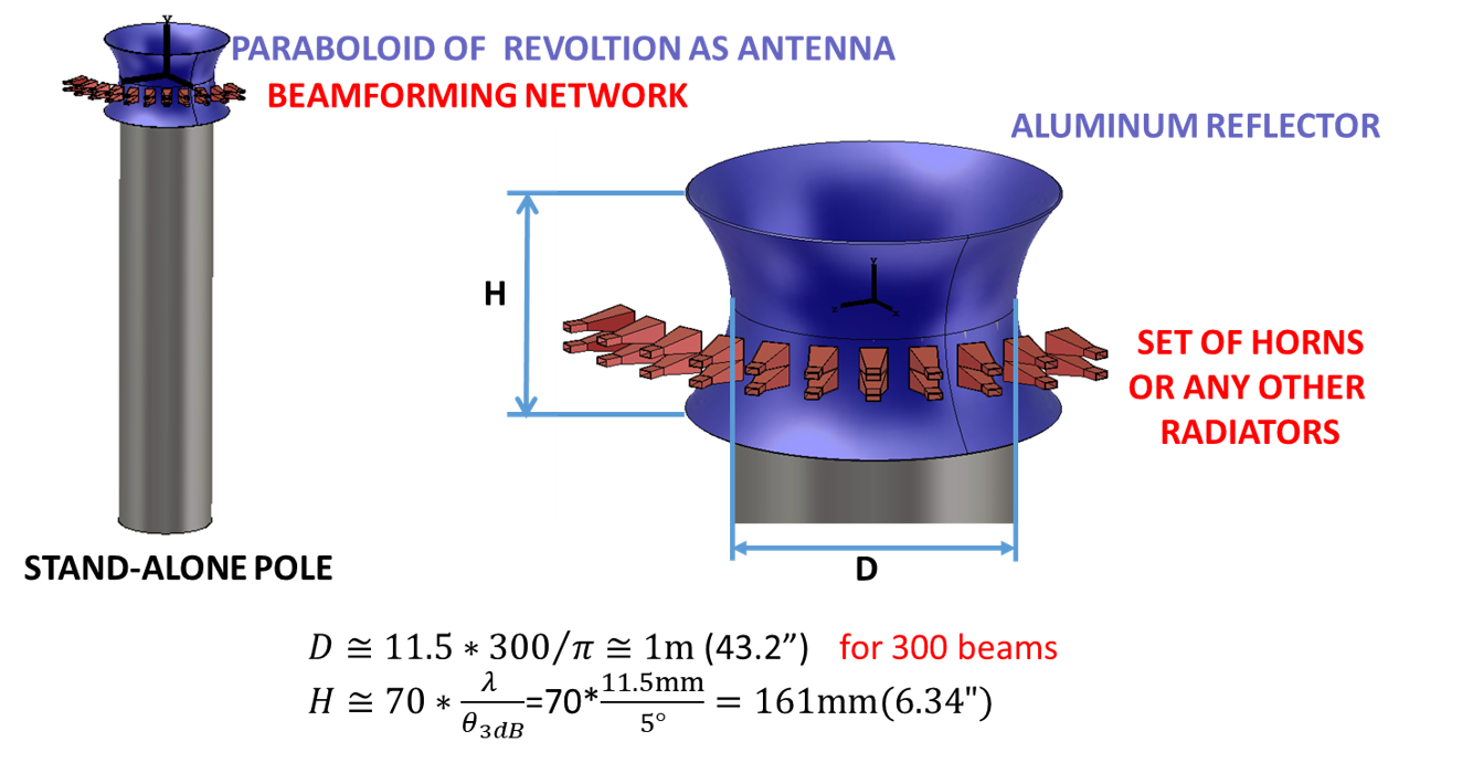
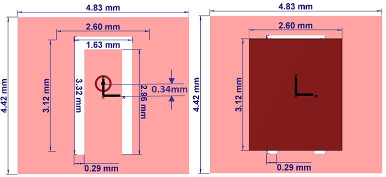
5G Switched-Beam Base Station Antenna
Expected Frequency Bands: 24.25 to 27.5 GHz, 31.8 to 33.4 GHz, 37.0 to 43.5 GHz, 45.4 to 50.2 GHz, 50.4 to 52.6 GHz, 66 to 76 GHz, 81 to 86 GHz.
Wavelengths at Central Frequencies: 11.5mm, 9.2mm, 7.45mm, 6.28mm, 5.82mm, 4.22mm, 3.59mm
Total Passband: 33 GHz in all Frequency Bands
Relative Passband : 12.6%, 4.91%, 16.14%, 10%, 4.27%, 14%, 6%
Total Number of Simultaneous Independent Beams is up to several hundred and depends on communication intensity. In dense urban high-rise scenarios with tall buildings and a high number of subscribers, an antenna with beam steering in both Azimuthal and Elevation directions is the most beneficial option.
Click on image to get to the text.

Radio-Frequency-Transparent, Electrically Conductive Graphene Nanoribbon Thin Films as Deicing Heating Layers
Ice-elimination systems are very common in large radio-frequency (RF) structures. They can be classified as either passive anti-icing films (preventing the accumulation of ice) or active deicing devices (removing ice after accumulation). Typically, an icing protection system is in radomes. Radomes are protecting shells or covers for radar instruments in aviation and marine environments. The radomes are subject to hostile environments, such as high winds containing sand, rain, hailstones, and saltwater, over wide temperature variations. Explosive pressure blasts can also take place nearby the radomes. Thus, radome deicing conductive films must be extremely tough with good adhesiveness to the heated surface. In addition, these deicing structures must not compromise the reliability of the original RF system, which, in the case of radome applications, means that the deicing film must be predominately transparent to RF radiation at any polarization with minimal impact on the antenna scan performance. It is desirable that this film be lightweight and low-cost, with physical characteristics that allow it to cover large curved surface areas.
Click on image to get to the text.
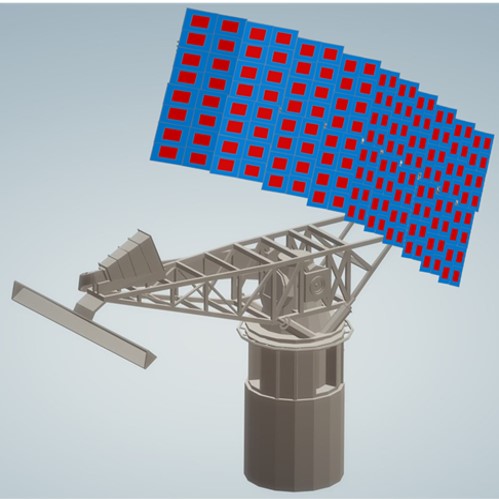
Reflect Patch Array for Radar
Overview. The proposed new antenna for AN/SPS-49 radar is expected to meet various requirements:
Incorporate electronic beam steering in elevation providing more than two elevation beams, incorporate cosec2 coverage, handle peak power delivered through the rotary joint up to 300 kW at 4% duty cycle, sidelobe reductions and beamwidth, the gain not less than 28 dBi measured relative to the RF power supplied by the rotary joint
Incorporate the electronic steering and stabilization of beams in the elevation plane (“row-board”) to lower overall and maintenance cost, extend the radar operational life and improve its reliability
No radome is required to meet antenna assembly weight constraints.
Click on image to get to the text.
Radio-Frequency-Transparent, Electrically Conductive Graphene Nanoribbon Thin Films as Deicing Heating Layers
Deicing heating layers are frequently used in covers of large radio-frequency (RF) equipment, such as radar, to remove ice that could damage the structures or make them unstable. Typically, the deicers are made using a metal framework and inorganic insulator; commercial resistive heating materials are often nontransparent to RF waves. The preparation of a sub-skin-depth thin film, whose thickness is very small relative to the RF skin (or penetration) depth, is the key to minimizing the RF absorption. The skin depth of typical metals is on the order of a micrometer at the gigahertz frequency range. As a result, it is very difficult for conventional conductive materials (such as metals) to form large-area subskin-depth films. In this report, we disclose a new deicing heating layer composite made using graphene nanoribbons (GNRs). We demonstrate that the GNR film is thin enough to permit RF transmission. This metal-free, ultralight, robust, and scalable graphene-based RF-transparent conductive coating could significantly reduce the size and cost of deicing coatings for RF equipment covers. This is important in many aviation and marine applications. This is a demonstration of the efficacy and applicability of GNRs to afford performances unattainable by conventional materials.
Click on image to get to the text.